
My uncle gave me this Autosuper Sebring Super 1 car radio to repair and add Bluetooth to. It started with a short circuit and a burning smell. What followed was weeks of systematic detective work, tracing signals through decades-old circuits, uncovering botched previous repairs, and slowly piecing together what went wrong inside a 1970s Autosuper Sebring Super 1. It is a beautiful piece of West German engineering that had been sitting silent for years.
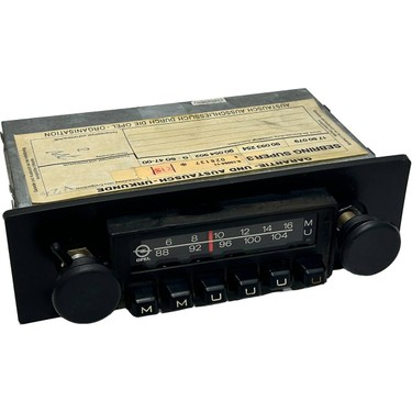

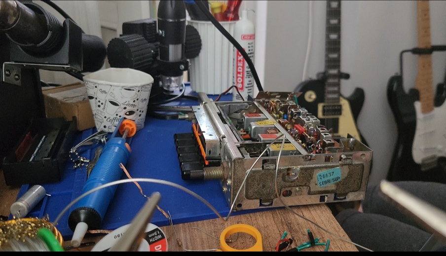
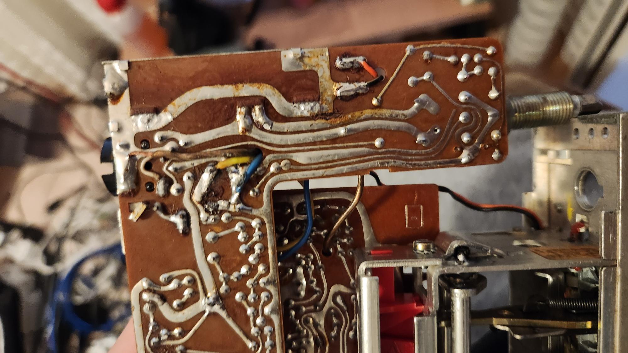
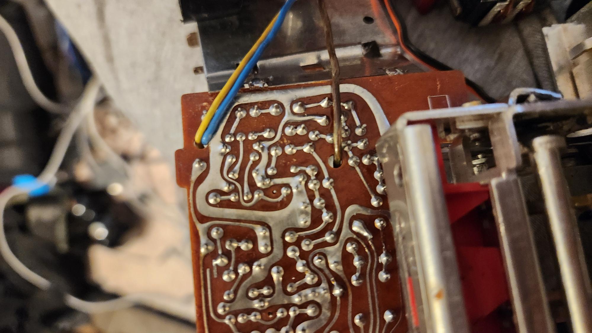
The Autosuper Sebring Super 1 (part number 10043-906.00) is a vintage AM/FM car radio from probably the mid-1970s. It's built on two separate PCBs: a main board housing the FM tuner and IF stages, and a daughterboard carrying the amplifier, tone controls, and power supply. The two boards are connected by three wires: yellow, blue, and a shielded brown/white cable. The whole unit is a compact, beautifully engineered piece of automotive hi-fi from an era when radios were built to last; if maintained.
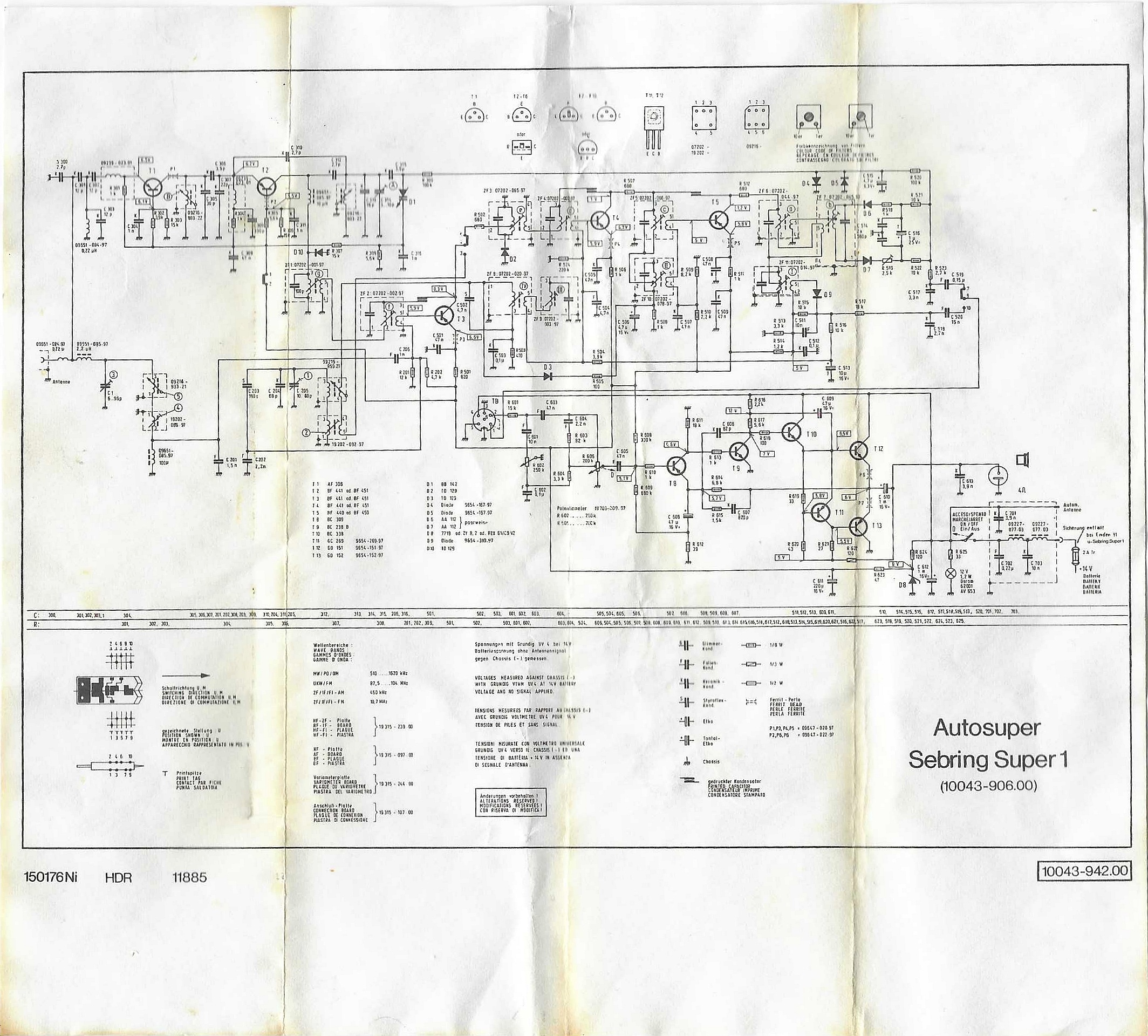
This one hadn't been maintained. It had been "repaired" very badly by an amateur before me. Surprisingly, it had its schematic inside, which was really helpful. This repair would have been impossible without the schematic. Here is the schematic if you have the same radio, as I was not able to find it online.
The very first symptom was alarming. When powered on, the input choke coil got dangerously hot within seconds, and there was a dead short to ground on the power rail. Something was pulling massive current.
The problem turned out to be diode D10, the polarity protection diode at the power input. It had failed internally shorted, essentially turning into a wire and creating a direct path from the power supply to ground. Well, it did its job; it sacrificed itself to protect the radio. But it was turning the choke into a space heater.
The fix: Replace D10 with a new rectifier diode. Immediately, the dangerous current draw stopped. The radio no longer tried to set itself on fire. Progress! I also confirmed from the schematic text that this radio uses a negative ground (chassis = minus), which is critical to know before connecting anything to a car's electrical system.
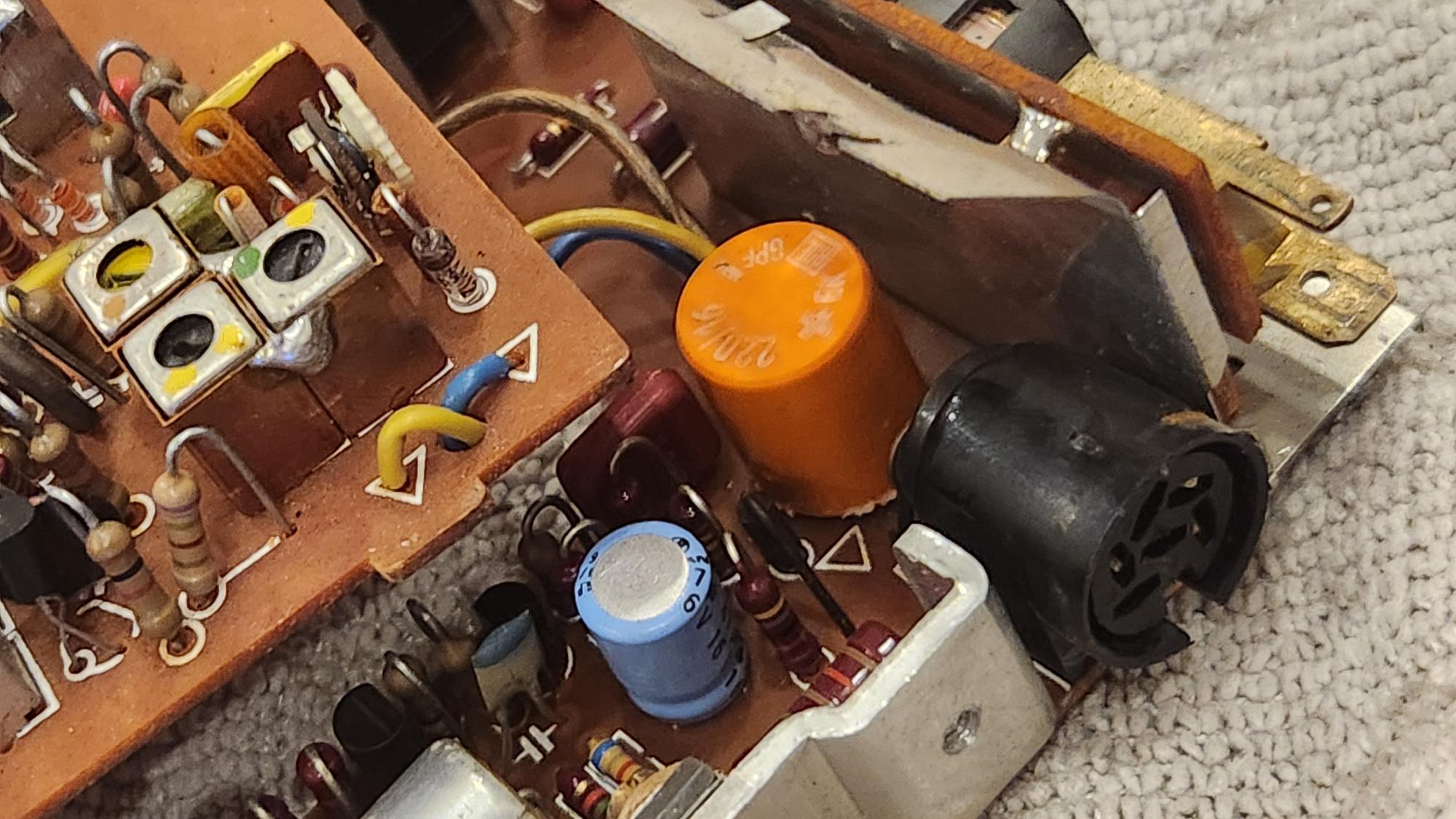
A radio from the 1970s means old electrolytic capacitors. These components have a liquid electrolyte inside that dries out over decades, causing them to lose capacitance, develop high internal resistance, or short-circuit entirely. I replaced them all one by one; even if some of the caps had survived, they would die soon. Those were high-quality German audio capacitors, so I kept them as a treasure and replaced them with high-quality Japanese equivalents. I also opted for higher voltage capacitors to extend their lifespan.

After replacing the diode and capacitors, I heard a hiss from the speakers. That meant the radio was working, but there was no audio yet. I started injecting audio into the circuit.
I started from the speaker output and moved towards the amplifier input, eliminating components one by one. (Pro tip: Always use a DC blocking capacitor, e.g., 0.1µF, in series with your probe to prevent DC voltages from the radio back-feeding into your phone or audio source).
First, I identified the output transistors. The GD151 (NPN) and GD152 (PNP) are housed in TO-126 packages. A quick check of the radiomuseum.org database confirmed these aren't germanium as you might expect from their age; they're silicon. This was good news, since silicon transistors are more robust, easier to work with, easier to find, and cheaper. They were cooled by a big piece of metal and seemed to be the main amplifier transistors.
Next, I checked the driver transistors: BC338 (NPN, T10) and BC328G (PNP, T11). They are a complementary pair feeding the push-pull output stage. Audio injected at their bases also produced music, though slightly less from the BC328G, which is normal.
Then came the preamp transistors, T8 and T9. I had to replace them, as they seemed to be dead. I used alltransistors.com to find alternatives. While buying them, I bought alternatives for all the transistors on the board just in case. I even found some replacement germanium transistors. The germanium transistors were part of the radio circuit, and I was a bit scared to replace them. I hoped it was best not to do so, as the IF circuit in these radios is factory-calibrated with multiple potentiometers.
Next, I tested the volume potentiometer, as pots tend to get oxidized. All three pins produced audio when probed (which makes sense—a pot is one continuous resistor strip, so a signal injected anywhere reaches everywhere). The center pin was quieter due to the wiper dividing the signal. The pot was healthy.
But the radio signal itself was still not working. Not even a hiss from either AM or FM.
The signal was dying somewhere between the input source and the pot. At this point I knew: Pot → T8 → T9 → T10 → T11 → T12 → T13 → Speaker all worked. So by using aux input I was able to connect a bluetooth module.
While testing, I fell into two pitfalls:
The 6-pin German radio socket is reversed in the schematic. So, when you look at the back of the radio, the connector is mirrored.
Pins 1 and 2 must be shorted from the outside. They designed it so that when an audio jack is connected, it disables the radio externally. I used a short jumper to bypass them for now.
I inspected the yellow and blue wires. They are actually connected to the same node in the circuit. In the schematic, you can identify the yellow cable as the one connected to R508 and then T8. The blue cable is shorted to that.
I then started checking the voltages given in the schematic. The first discovery was devastating in its simplicity. Someone had previously replaced the 8.2V Zener diode (which provides regulated voltage to the entire FM tuner section) with a 1N4007, a standard rectifier diode! Instead of regulating at 8.2V, a 1N4007 drops only 0.7V. This meant the FM tuner's transistors were being fed approximately 13V instead of 8.2V nearly double the intended voltage.
I replaced it with a proper 8.2V Zener. The voltage now measured correctly at 8.2V. But the FM was still dead.
Measuring voltages on T5 (one of the IF amplifier transistors) revealed something bizarre: Base = 0.11V, Emitter = 7.5V, Collector = 6.78V. A base sitting at essentially zero volts means the transistor isn't receiving any bias. It's completely shut off.
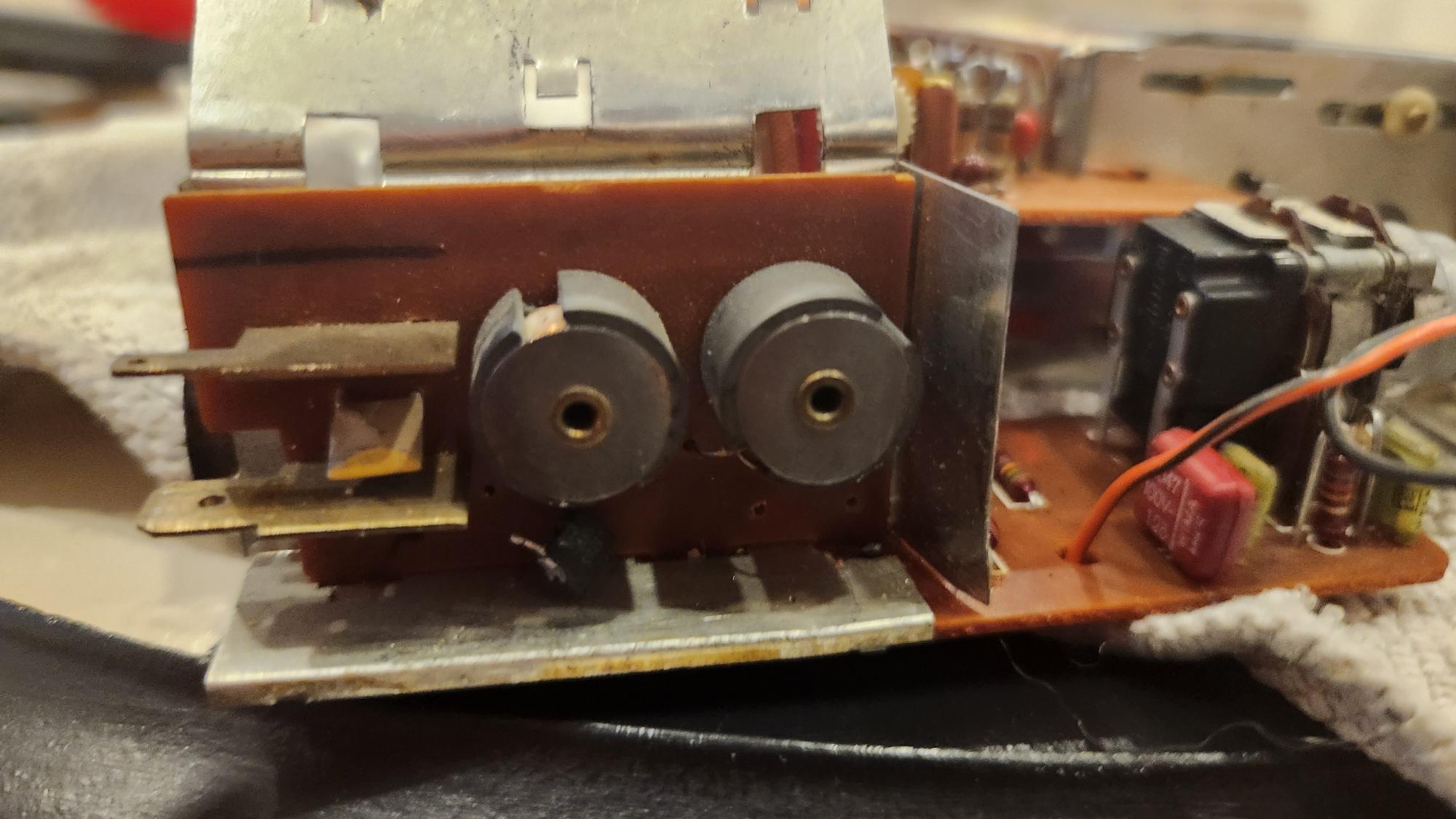
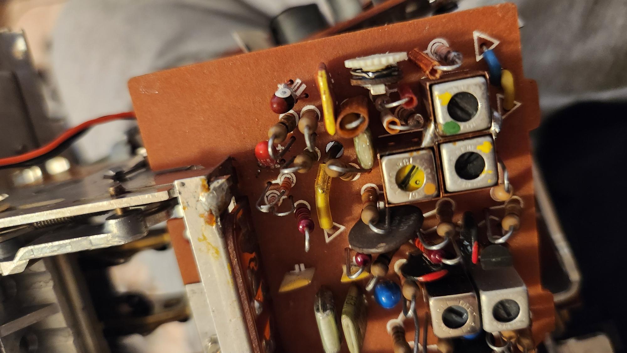
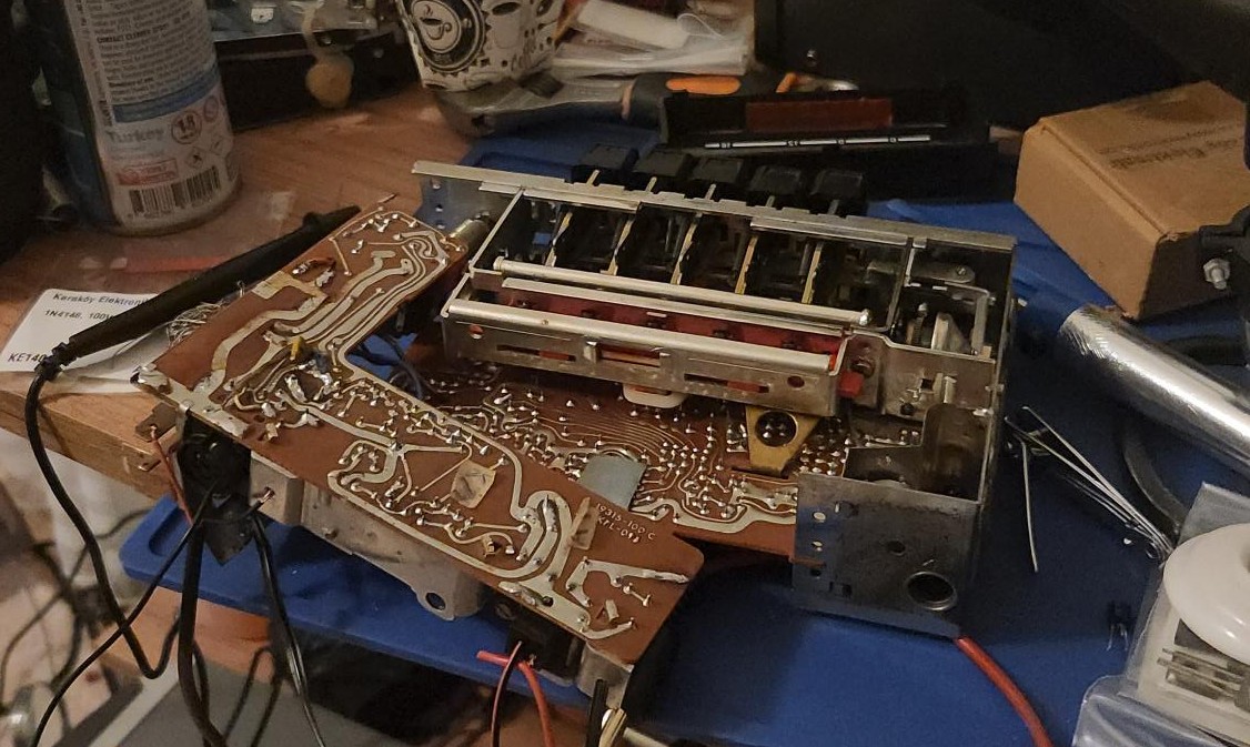
When I looked at what was physically installed in the T5 position, I found a BF198, an NPN transistor. The schematic calls for a BF440 or BF450, both PNP types. Someone had installed an NPN transistor and rotated it, apparently thinking you can turn an NPN into a PNP by flipping it around.
You can see the wrong transistor on the far left of the photo. As you can see, the legs are twisted.
You absolutely cannot do this. NPN and PNP transistors have fundamentally different internal semiconductor structures. Rotating an NPN just connects all the pins to the wrong junctions. The transistor was never going to work in this configuration.
I sourced a BF440 and installed it in the correct PNP orientation. I also verified that T1-T4 had their correct original transistors (the previous repair person only got to T5 before presumably giving up).
Lastly, I carefully cleaned the board with contact cleaner to remove any oxidation.
There are some lessons I want to share;
The two biggest issues; the wrong zener and the wrong transistor were both caused by a previous repair attempt. Always check what's already been "fixed.". Please if you don't know what you are doing, stop trying to repair them. Don't break these delicate devices.
A phone playing music and a wire is the most powerful diagnostic tool for audio circuits. Start from the speaker, work backwards. Where the music stops, the fault lives.
No amount of rotating, flipping, or wishful thinking will change the fundamental physics of semiconductor junctions.
After careful consideration, I decided to add Bluetooth through the 6-pin connector using an external 3D-printed unit for the buttons and microphone. I do not want to alter or hurt this beautiful piece of hardware. I will be sharing the .stl files later on!
The Autosuper Sebring Super 1 is alive. The amplifier works perfectly, pushing clear, powerful audio through the original speaker. FM reception is fully operational. Parts have been ordered for a complete recap and transistor refresh.
Fifty years after it rolled off the Blaupunkt/Grundig production line in West Germany, this little radio is playing music again. Not bad for a patient that arrived with a burning coil, a dead short, and two completely wrong components.